ESPs (electrical submersible pumps) are employed throughout the oil industry.
They are an efficient and reliable, artificial-lift method for pumping moderate to high volumes of fluids from wellbores.
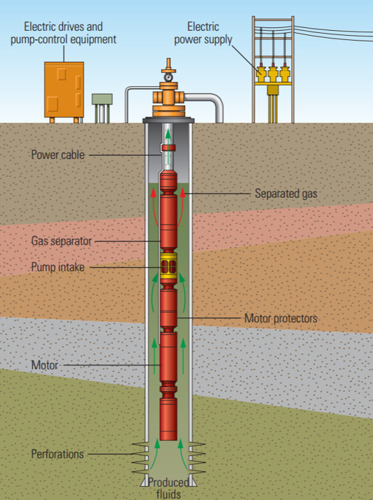
They comprise of a series of centrifugal pump stages contained within a protective housing mated to a submersible electric motor, which is controlled by a VFD. It is installed at the end of the production tubing with an armour-protected cable connecting the pump to electric power and surface controls. This cable can be over 1km long. The general arrangement of an ESP is shown below (Fig. 1) :
Variable speed ESPs are especially appropriate for moderate-to-high-production rate wells, including highly deviated wells and remote, subsea deep-water wells. As production rates decrease, the pump motor can be slowed down via the VFD to accommodate the slower rate, without an expensive well intervention.
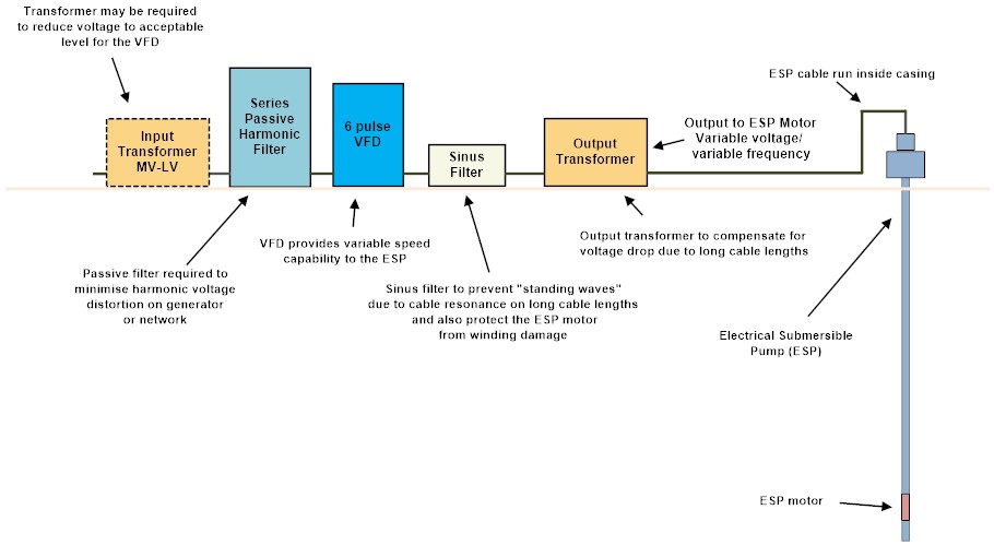
However, ESP VFDs usually cannot be installed without other ancillary equipment. The equipment, additional to the VFD, is depicted above and comprises :
- An input transformer to reduce the voltage to an acceptable level for the VFD.
- An input harmonic filter (passive, series wide spectrum types are popular) to reduce the harmonic voltage distortion at the generator or utility side.
- An output sinus filter. Required due to the interaction between the modulated VFD output voltage and the ESP cable capacitance can result in disruption to the VFD and failure of the ESP motor.
- An output transformer to compensate for the cable voltage drop down to the hole to the to the ESP motor in the reservoir.
This additional equipment results in a significant cost (e.g. the harmonic filter can cost more than the 6 pulse VFD alone at smaller ratings). The resultant overall physical space requirement can be an issue offshore and on skid mounted ESP packages.
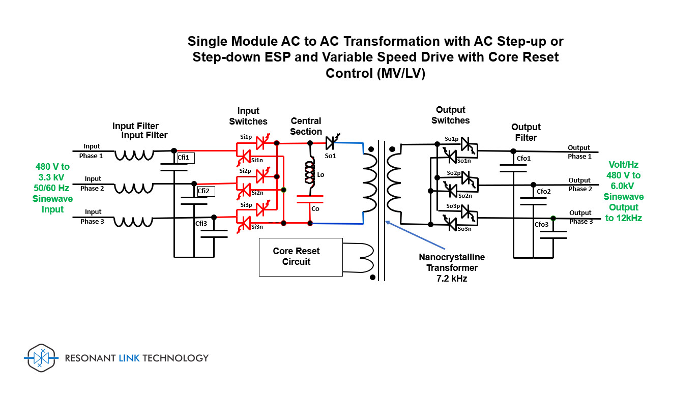
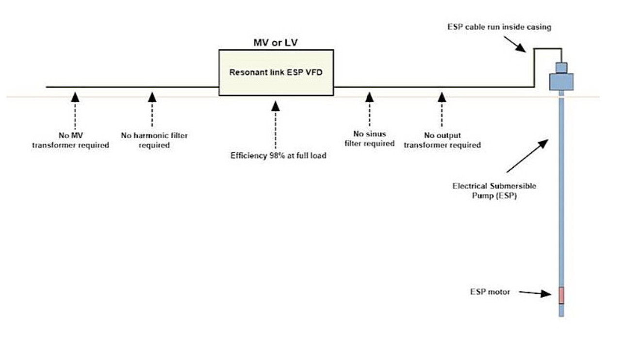
The ideal solution may be the utilisation of a Resonant Link ESP VFD. This drive is designed to totally replace the input transformer input harmonic filter, 6 pulse VFD, output sinus filter AND the output transformer. With a total harmonic current distortion (THDi) of <2% it complies with all present and future harmonic requirements.
The sinusoidal output voltage/frequency, up to MV (6.0kV is shown), can be optimised electronically to match the exactly ESP motor voltage/frequency requirements including for high frequency permanent magnet motors.
The physical size of the Resonant Link ESP VFD in either the LV or MV format is estimated to be less <10-15% maximum of that currently required for conventional technology (i.e. input transformer, harmonic filters, VFD, sinus filter and output transformer). Similarly, a cost comparison would be in the order of 50- 70% less than present systems. Fig 4 clearly demonstrates the benefits of the Resonant Link ESP VFD.
LV and MV versions would be available including IP54 versions for outdoor use in desert climates at up to 55 deg C ambient.
Note: Resonant Link DC Power Systems can also be applied in common DC bus or DC ring main configurations for multiple conventional VFDs for ESP applications, whether onshore or offshore.
In these applications the active AC-DC transformer(s) supplies the regulated DC power (and short circuit protection) to the conventional VFD IBGT output inverters.


